From bespoke seats to titanium arms, 3D printing is helping Paralympians gain an edge

Jeff Crow/AAP Image

Authors: James Novak, The University of Queensland | Andrew Novak, The University of Technology Sydney

** Please note: this is a copy of an article I wrote for The Conversation, published on 3rd September, 2021, and is shared under a CC-BY-ND license. You can access the original article by clicking here.**

Major sporting events like the Paralympics are a breeding ground for technological innovation. Athletes, coaches, designers, engineers and sports scientists are constantly looking for the next improvement that will give them the edge. Over the past decade, 3D printing has become a tool to drive improvements in sports like running and cycling, and is increasingly used by paralympic athletes.

The Paralympics features athletes with a diverse range of abilities, competing in a wide range of different categories. Many competitors use prosthetics, wheelchairs or other specialised components to enable them to perform at their best.

One interesting question is whether 3D printing widens or narrows the divide between athletes with access to specialised technologies, and those without. To put it another way, does the widespread availability of 3D printers — which can now be found in many homes, schools, universities and makerspaces — help to level the playing field?

Forget mass production

Mass-manufactured equipment, such as gloves, shoes and bicycles, is generally designed to suit typical able-bodied body shapes and playing styles. As such, it may not be suitable for many paralympians. But one-off, bespoke equipment is expensive and time-consuming to produce. This can limit access for some athletes, or require them to come up with their own “do-it-yourself” solutions, which may not be as advanced as professionally produced equipment.

3D printing can deliver bespoke equipment at a more affordable price. Several former paralympians, such as British triathlete Joe Townsend and US track athlete Arielle Rausin, now use 3D printing to create personalised gloves for themselves and their fellow wheelchair athletes. These gloves fit as if they were moulded over the athlete’s hands, and can be printed in different materials for different conditions. For example, Townsend uses stiff materials for maximum performance in competition, and softer gloves for training that are comfortable and less likely to cause injury.

3D-printed gloves are inexpensive, rapidly produced, and can be reprinted whenever they break. Because the design is digital, just like a photo or video, it can be modified based on the athlete’s feedback, or even sent to the nearest 3D printer when parts are urgently needed.


Read more: Paralympians still don’t get the kind of media attention they deserve as elite athletes


Harder, better, faster, stronger

An elite athlete might be concerned about whether 3D-printed parts will be strong enough to withstand the required performance demands. Fortunately, materials for 3D printing have come a long way, with many 3D printing companies developing their own formulas to suit applications in various industries – from medical to aerospace.

Back in 2016, we saw the first 3D-printed prosthetic leg used in the Paralympics by German track cyclist Denise Schindler. Made of polycarbonate, it was lighter than her previous carbon-fibre prosthetic, but just as strong and better-fitting.

With research showing sprint cyclists can generate more than 1,000 Newtons of force during acceleration (the same force you would feel if a 100-kilogram person were to stand on top of you!), such prosthetics need to be incredibly strong and durable. Schindler’s helped her win a bronze medal at the Tokyo games.

Denise Schindler on her way to a medal in Tokyo. Thomas Lovelock

More advanced materials being 3D printed for Paralympic equipment include carbon fibre, with Townsend using it to produce the perfect crank arms for his handbike. 3D printing allows reinforced carbon fibre to be placed exactly where it is needed to improve the stiffness of a part, while remaining lightweight. This results in a better-performing part than one made from aluminium.

3D-printed titanium is also being used for custom prosthetic arms, such as those that allow New Zealand paralympian Anna Grimaldi to securely grip 50kg weights, in a way a standard prosthetic couldn’t achieve.

Different technologies working together

For 3D printing to deliver maximum results, it needs to be used in conjunction with other technologies. For example, 3D scanning is often an important part of the design process, using a collection of photographs, or dedicated 3D scanners, to digitise part of an athlete’s body.

Such technology has been used to 3D-scan a seat mould for Australian wheelchair tennis champion Dylan Alcott, allowing engineers to manufacture a seat that gives him maximum comfort, stability and performance.

3D scanning was also used to create the perfect-fitting grip for Australian archer Taymon Kenton-Smith, who was born with a partial left hand. The grip was then 3D-printed in both hard and soft materials at the Australian Institute of Sport, providing a more reliable bow grip with shock-absorbing abilities. If the grip breaks, an identical one can be easily reprinted, rather than relying on someone to hand-craft a new one that might have slight variations and take a long time to produce.


Read more: 3 reasons why Paralympic powerlifters shift seemingly impossible weights


All these technologies are increasingly accessible, meaning more non-elite athletes can experiment with unique parts. Amateurs and professionals alike can already buy running shoes with 3D-printed soles, and 3D-printed custom bike frames. For those with access to their own 3D printer, surf finscycling accessories and more can be downloaded for free and printed for just a few dollars.

However, don’t expect your home 3D printer to be making titanium parts anytime soon. While the technology is levelling the playing field to a certain extent, elite athletes still have access to specialised materials and engineering expertise, giving them the technological edge.


This article was co-authored by Julian Chua, a sports technology consultant at ReEngineering Labs and author of the Sports Technology Blog.

3D Printed Sea Urchin Light

IMG_20200301_Sea Urchin Light

This project has been a little while in the making and it’s exciting to finally be writing about it. About a year ago I posted about 3D scanning some shells, and as part of the scanning I captured a sea urchin shell. At the time I didn’t know what I’d do with it, but fast forward a year and I’ve found a perfect application; turning the sea urchin shell into ceiling light covers in my house.

Sea Urchin GIFIn this post I’ll go over the main processes and experiments I went through to get the finished product, but in case you’re just here for the big finale, here’s the link so you can download the final Sea Urchin Light exclusively from my Pinshape account and 3D print as many as you like!

3D Scanning

ScanAs explained in further detail in my previous post, I used an EinScan Pro 2X Plus 3D scanner, which included a turntable to automatically capture all angles of the sea urchin shell. This resulted in a full-colour, highly detailed model of the shell, as shown to the right. However, as anyone familiar with 3D scanning will know, this model is just a skin with no thickness or solid geometry, and was just the starting point for the design process.

Design

If you don’t have access to expensive CAD programs, good news; this project was completely designed in free software! I’ve used Autodesk Meshmixer for many of my tutorials and posts, it’s a surprisingly powerful tool and a must for anyone involved in 3D printing. Additionally, it’s quite useful when you are working with 3D scan files, which are typically a mesh like a STL or OBJ. The process took a little time, but has been outlined in 6 basic steps below:

IMG_20200301_Sea Urchin Meshmixer Tutorial

  1. Fill any holes and errors in the 3D scanned sea urchin shell. In Meshmixer, this simply involves using the “Inspector” tool under the “Analysis” menu.
  2. Scale up the shell to the appropriate size, then use the “Extrusion” tool to thicken the skin into a solid shell. So that the shell would allow a lot of light through, I used a 0.7mm thickness for the overall design.
  3. I wanted to create an interesting pattern when the light was turned on, so separated several areas of a copy of the original mesh to be used to create thicker sections. This was a slow process of using the brush selection tool to remove areas, before repeating step 2 with slightly thicker geometry. For this design I ended up with 3 different thicknesses around the shell.
  4. To allow the light fitting within the shell, a larger opening was needed at the top. A cylinder was added from the “Meshmix” menu and placed in the centre.
  5. By selecting both the shell and the cylinder together, the “Boolean Difference” command became available, subtracting the cylinder section from the shell.
  6. Lastly, a neck section measured off the original light fitting was added. I cheated slightly and modelled this in Autodesk Fusion 360 (also free if you’re a student), but you could use Meshmixer – it would just take a bit longer to get accurate measurements. Then the separate parts are joined together using Boolean Union, and the design is finished.

3D Printing

As well as the new design needing to fit the geometry of the existing light fixture, it also needed to fit the build volume of the 3D printer – in this case a Prusa i3 MK3S. As you can see below, the shell is only slightly smaller in the X and Y dimensions than the build plate.

IMG_20200130_Shell on Prusa i3 MK3S

In terms of print settings, I stuck with some pretty typical settings for PLA, including a 0.2mm layer height. Support material is necessary with the light printed with the neck down – this is the best orientation in terms of ensuring the surfaces visible when standing below the light (remember, it is ceiling mounted) are the best. Where support material is removed is always going to be messy, and you wouldn’t want to have these surfaces being the most visible. Overall, this meant that each light took ~32 hours to print.

Material & Finishing

One of the steps that took a bit of experimentation was choosing the right material in order to look good when the light was both on and off. Each of these lights are the main, or only, sources of light in the spaces they are installed, so they need to provide a good amount of light.

IMG_20200218_Sea Urchin Light Materials

As shown above, 3 different materials/finishes were trialled. Initially I began with a Natural PLA from eSUN, which is a bit like frosted glass when printed. While this allowed all the light to escape and illuminate the room, most of the detail was difficult to see in both the on and off settings. It was just like a random glowing blob. I then tried pure white PLA, hoping that the print would be thin enough to allow a reasonable amount of light out. Unfortunately very little light escaped, however, the shadows from the different thicknesses looked excellent, and when the lights was off, it was very clear this was a sea urchin shell. Perhaps this would be a good option for a decorative lamp, but not so good for lighting a whole room.

So the “Goldilocks” solution ended up being in the middle – I 3D printed the shells in the translucent Natural PLA, and then very lightly spray painted the exterior with a matt white paint. Just enough to clearly see that it is a sea urchin shell when the light is off, and translucent enough to allow a lot of light out. Perhaps there is a material/colour of filament that would achieve this with needing to paint, but I didn’t want to have to buy rolls and rolls in order to find it. PETG would be interesting to try, and if you have any other suggestions, please leave them in the comments section.

The Result

IMG_20200219_143458 Dimensions Crop
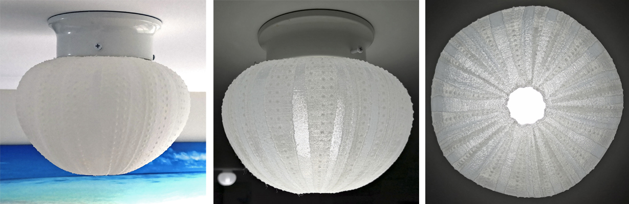
To the right are the dimensions of the ceiling light fixture within which the sea urchin light comfortably fits. The light itself is a standard B22 fitting, so the sea urchin can comfortably fit most standard interior lights. However, if you have a different sized fitting, or want to fit it over an existing lamp, you can easily scale the design up or down to suit your needs. I’ve already fitted one of the early small test prints over an old Ikea lamp, it just sits over the top of the existing frame. In total I’ve now installed 5 of the large ceiling light covers in my house, and am planning a new design to replace some of the others (my house is full of this terrible cheap fitting!).

As mentioned at the beginning of this post, I have made this design exclusively available on Pinshape – it’s just a few dollars to download the file, and then you can print as many as you like! If you 3D print one, please share a photo back onto Pinshape, I love seeing where my designs end up and what people do with them.

– Posted by James Novak

Mannequin Head Remix

3D Print Mannequin Head

Close but no cigar.

Sometimes you find something close to what you want on Thingiverse, Pinshape or other 3D printing platforms, but it’s just not quite right. Well, there is often something you can do about it, and it won’t cost a cent.

I’ve written several tutorials about using free software Meshmixer to make various modifications, for example creating a mashup of 2 different files or adding some text to a design. On this occasion I found a 3D scan of a styrofoam mannequin head on Thingiverse, which included all of the messy details you’d expect from a foam model (smaller head in the image above right). Great if you’re after realism, but not great when you want nice smooth surfaces for 3D printing. The model was also not at the correct scale, and I wanted a mannequin head to use as a model.

The scale was an easy fix, and of course could be done in your slicing software.  Cleaning up the surfaces was also quite simple using the ‘Sculpt’ tool and choosing one of the smoothing brushes. This essentially irons out all the rough details, smoothing out the model as you brush over it. A few minutes of work and a rough model is now clean and ready for 3D printing – which of course I’ve uploaded as a remix on Thingiverse so you can download it for yourself.

The above left image shows the 3D printed result from a Creality CR-10 S5, a very cheap, very large FDM machine with a build volume measuring 500x500x500mm. Obviously my settings weren’t great, the seam is in the worst possible position, and because I wanted a quick result I used only a single wall thickness and almost no infill, which split apart at the top. However, it’s fine for my purposes, and the surface quality on most of the model is fantastic.

Happy smoothing!

– Posted by James Novak

Update 20/02/2023

Below is an image showing the dimensions of the model around the head where you might need to fit a helmet or hat (in mm). If you need larger/smaller, you can just scale the model to suit.

3D Scanning Natural Forms

IMG_20190117_3D Scan EinScan Pro

This is a post about my new favourite toy – the EinScan Pro 2X Plus 3D scanner from Shining 3D. Why? Because it allows you to turn any object into a 3D model! And I can tell you upfront, it works REALLY well!

This is not the first 3D scanner from Shining 3D, which is a good sign that both their hardware and software has had time to mature. The EinScan Pro 2X Plus is brand new to the market, which means there are not many reviews at the time I’m writing, although you can find a brief overview from 3D Scan Expert and will no doubt see a full review from him in the near future. I’m not a 3D scanning expert, so am not going to dive into all the details here. I have used several scanners in the past and written a few posts, but this is the first that I have full access and control over and am currently using on a daily basis.

Enough with the introductions. One of my first experiments has been to 3D scan some challenging organic forms, including some shells which I picked up from the beach. The top photo shows one of these shells being scanned (we have the “Industrial Pack” turntable and “Colour Pack” upgrades for the scanner). The process is straight forward in the accompanying EXScan Pro software – a few basic settings about the detail you’d like to capture and press go. The turntable and scanner do the rest, and you can see the points being captured in real-time on screen. There is a bit of cleanup after the first scan to remove any points that aren’t needed (e.g. you can see in the photo some points around the perimeter where the scanner picked up an edge of the turntable), at which point you have your first scan.

This could be all the detail you need depending on your application; however, all you have is an outside collection of points, with no detail about the inside of the shell. So I then flipped the shell over and performed a second scan. The only difference from the previous step is that now there are 2 scans. Amazingly the software is proving quite intelligent at automatically aligning multiple scans, finding common points and bringing them all together. This doesn’t always work, and there is an option to manually align 2 scans by selecting 3 common points in each. I must admit the interface for this process is quite painful to use at the moment, so it’s always great when the software automatically does this. Overall the software is very basic, you really don’t have a lot of control – which can be both a blessing and a curse. You certainly can’t perform any sort of editing actions other than selecting and deleting points.

The final step is to turn all of the points (aka. point cloud) into a mesh suitable for 3D CAD software, or 3D printing. There is an option to create a watertight mesh, letting the software automatically fill any holes in the model. For this shell scan I only had very minor gaps which were nicely cleaned up and blended into the mesh. However, I have found with some other scans that if holes are quite large, or there are some messy overlaps in scan data, the software will produce some weird results – best to keep scanning to capture as much data as possible before creating a mesh, once you get to this step there is no turning back.

IMG_20190118_3D Print Shell

Best of all, being a watertight mesh, the file can be immediately used for 3D printing. But why simply replicate a shell? I always see large shells as decorator items in stores retailing for hundreds of dollars – and now I can 3D print them for a fraction of the price. This one was scaled up 500% and printed on a Wanhao Duplicator D9/500 – which is still working somewhat consistently after my previous post and firmware upgrades. I decided to print it in an upright orientation so that the 0.5mm layers are similar to the layers naturally occurring in the shell. Even though the print quality is still quite rough, I think this only adds to the natural effect.

The shell has been saved as a .obj file, meaning that it has all the colour information along with the geometry that would normally be a .stl file. I have shared this on Sketchfab so that you can have a closer look at the mesh in 3D using the above viewer. I think it’s a really great result, and hopefully you can see why I have called this my new favourite toy. It really does open up new opportunities (perhaps you’ve already seen some new experiments if you follow me on Instagram). Stay tuned, I’m sure there’ll be plenty more posts that involve 3D scanning and 3D printing in the future.

– Posted by James Novak

Cowtech 3D Scanner – The Build

20160729_Cowtech Ciclop Build

3D scanning has featured a few times on my blog (eg. see my custom virtual reality headset which perfectly fits my face), so it was only a matter of time until I bought a scanner for myself. Earlier in the year Kickstarter convinced me to help fund the Ciclop 3D Scanner from Cowtech, a $99 open-source system that was impossible to refuse. Yep, $99!

Well here it is, built over a couple of days and making me feel like a kid again with a new kit of Lego. I bought the cheapest version of the scanner, choosing to 3D print the components myself (naturally!) which can be freely downloaded from Thingiverse. These worked really well, only a few areas where support material was time-consuming to remove, and were all done on the small build plate of the UP Plus 2. The top left photo shows most of these 3D printed parts (12 in total needed).

20160805_Cowtech BrokenAfter receiving the other scanner hardware from Cowtech this week, it was finally time to put this kit together – no simple task after I snapped one of the key parts early in the assembly process! You can see the 2 broken pieces of acrylic to the left, which are both from the long arm connecting the 2 main octagonally-shaped hubs in the middle photo at the top of the page. So far Araldite seems to be holding them, and this snapping seems to be a common problem people are reporting – maybe a bit better tolerances required in the laser cut pieces, or a different material that’s not quite so brittle.

Otherwise the assembly process has been quite straight forward, the video provided by Cowtech is very easy to follow, especially if you’re a little familiar with Arduino’s. There are some really clever details in the way nuts slot into the laser cut pieces and screws slide through the 3D prints that I’ve never seen before, so as a designer it was fun to discover these details. I really appreciate the tolerances for many of the different parts fitting together, from laser cut to 3D print to machined screws, I am honestly surprised how well they all came together for me. So in the top right image you can see the final result – I have to admit I feel like an extra 3D printed part is required to cap off the top above the camera, it doesn’t look right to me so this might be something I make myself soon.

The challenge I’m having now is that I can’t get my camera to be recognised by the recommended open-source software for the scanner, Horus. I’ve spent hours installing software and drivers, rebooting my computer, uninstalling, installing in a different order, rebooting… Nothing is working. Hmmm, a bit frustrating but as I’ve learned with these sorts of new products from Kickstarter, sometimes it can take some time for people to start posting solutions and updates as my order was dispatched quite early and there is just not much up on the forum yet. Hopefully soon!

Keep an eye out on my blog for updates, and hopefully soon some successful 3D scans!

– Posted by James Novak

Update 7/8/2016:

Settings That Work CroppedAfter some ideas from the Cowtech Facebook Group, I have solved the connectivity problem – hopefully it helps anyone else that reads this. Firstly the Cowtech Scanning Guide says to plug in the camera to set it up in Horus – but you actually need to plug in the entire scanner – 2 USB’s and power. I then went into the preferences, selected the appropriate camera and serial, then changed the Arduino type to “Arduino Uno” and clicked “Upload Firmware” (shown left). I had to close and then re-open Horus, but now it’s all up and running. Hopefully the rest of the calibration goes a little smoother. I think the instruction booklet from Cowtech needs to make this clearer, and include these preference changes.

June Events

20160617_3D Workshop School

It’s been a busy month for me and 3D printing even though it’s meant to be the mid year break from uni! Above are some photos from a full day 3D printing workshop I ran for a local high school in our new 3D printing lab, with a handful of students all being exposed to CAD, 3D printing and 3D scanning for the first time. By the end of the first session each of them had their first small design 3D printing over the lunch break, which just shows how quickly young kids are able to pick up this technology. We were also able to demonstrate for the very first time one of our brand new chocolate 3D printers, the Choc Edge. Yes that’s right, a chocolate 3D printer! I’m sure it won’t be long before everyone has something like this on their kitchen bench, but for now if you want to see how they work, come along to our Gold Coast campus open day on July 24th where we will have 3 in action for your sugary delight!

20160621 Innovation Brisbane

Last night I was really privileged to be a speaker at an event called DRIVEinnovation, hosted by the Brisbane West Chamber of Commerce. As the name suggests, the discussion was all around innovation, and how businesses can better adopt new technologies and keep up with the rapid changes across all industries. I was part of a panel with Ty Curtis from local augmented reality company Activate Entertainment, and Sam Forbes from cloud services company 6YS. The questions were certainly challenging in the short time-frame (how do you even begin to describe how to innovate in just a few short minutes?), but it’s really great to see such an active council asking these questions and building a community of very talented people. There were even some virtual reality and augmented reality demonstrations (that’s me in the right photo looking at a human skeleton with augmented reality). If you’re in the local area, it’s definitely worth following the Chamber through email or social media as these events happen every few months.

Coming up next week, and running over 2 weeks, are some intensive workshops at Griffith University for teachers. The workshops run in 2-day blocks, costing $180 (which also allows you to bring a student for free), and are on the following topics:

  • InDesign (beginner and advanced)
  • Photoshop (beginner and advanced)
  • 3D Animation (beginner and advanced)
  • Games Design (beginner and advanced)
  • Hand Lettering
  • 3D Design
  • 3D Printing (beginner and advanced)
  • Design Modeling Techniques

I will of course be running the 3D printing workshops, and there will be 2 levels of workshops each week: Workshop 1 is for beginners to CAD and 3D printing, where people will get to build a functioning product assembly. Workshop 2 is for more intermediate users who have some experience with CAD and 3D printing, and we will be combining this knowledge with 3D scanning to create wearable devices. If you’re interested, get in touch and I’ll pass on details to the administrator organising the event.

– Posted by James Novak

Cyclops – Step 1

150623 Cyclops

With a costume party fast approaching I couldn’t turn up without at least some part of my outfit 3D printed could I? Originally I had planned to go as Thomas from Daft Punk after finding the helmet files on Thingiverse, however this is a seriously involved 3D print with around 30 pieces to print, glue, smooth, paint and install electronics! As much as this would be an awesome project, I can’t really justify that amount of time, and probably wouldn’t finish it in time anyway. Searching for something smaller, Cyclops from X-Men became my next option – I’ve never been a fan of the movie version played by James Marsden, but growing up watching the cartoon version he was always my favourite. The best image I could find of the goggles is on the left.

A quick look on Thingiverse didn’t bring up anything that really looked any good, so today’s job has been to model the trademark goggles worn by Cyclops (not the lame looking sunglasses!). I’ve previously had a 3D scan of my face done, and used it to build a perfect-fitting Virtual Reality headset – this seemed like a great starting point to get the dimensions correct. Originally I was going to make these goggles fit perfectly as well, using the surfaces of the 3D scan to shape them. However I’d like to share this design on Thingiverse, and doubt there are too many clones of me out there who would fit it! So I’ve just used the scan to get the sizing correct for my face, and kept the geometry much more generic so that it should suit most people, perhaps with some scaling to shrink/enlarge it for different head shapes. You can see how I’ve modeled half of the design in Solidworks in the right image, with the biggest challenge being to get the eye-slot in the right spot and the rest of the geometry proportional around this. The slot is quite narrow so it needs to be correct or I won’t be seeing very much!

150624 Cyclops

I have sliced the model up into 4 sections so that it can be printed on the small print plate of my Up! Plus 2 3D printer – notice the small slots I’ve added to allow for easy alignment and gluing. Now just to print, glue, paint, and figure out how to achieve the red eye-piece and light it up. Once that’s all done and I know it works (fingers crossed!) I’ll upload it to Thingiverse 🙂

– Posted by James Novak

Personalised Virtual Reality

150227 Custom VRA few days ago I wrote about having used 3D scanning to create a test 3D print that perfectly fits the contours of my face. You can check it out here. The next step has been to prototype a simple design for a virtual reality (VR) headset using the scan data of my face, along with the specific dimensions of my phone. Through some earlier testing of Google Cardboard and a 3D printed Thingiverse VR headset, the biggest problems I found were:

  1. The headsets never comfortably fit my face
  2. The adjustable lenses are very fiddly to adjust and keep in the optimal position for my eyes
  3. My phone never properly fits, requiring additional padding

My idea with this particular design has been to address each of these issues separately through the power of 3D printing. So firstly, the main headset uses the 3D scan data of my face – this could easily use anyone’s face, creating a perfect fit. Secondly, the lenses have been located in the correct position for my eyes, and focal length of the lens used. Again, this could easily be adjusted to suit anyone’s eyes and lens. Thirdly I have created a separate frame to hold the phone which snaps onto the main  headset. A variety of these could be developed to hold any phone model. In essence, I’m imagining a VR headset that can be customised to suit anyone, and modified as they upgrade their phone using modular components.

2015-02-27 10.10.54While the theory is all good, this particular print isn’t perfect – it’s only the first prototype. There is some distortion in the main headset where the print began to lift off the plate during printing, so modules don’t perfectly fit (this is exacerbated by the fact I had to split parts to fit on my Up! Plus 2 printer and glue them after). The lenses aren’t 100% perfectly located, distorting the image. It’s close, but when you’re dealing with lenses close enough is not good enough! So maybe a small amount of adjustability will need to be built in. The phone is also a little loose in the frame, but this is an easy fix. So plenty of work to go, but at the same time an exciting start! If you want to check it out it will be at the Brisbane Virtual Reality Club‘s next meeting.

– Posted by James Novak

Immortalised Through 3D Scanning

150223 3D Scan FaceSince playing around with some 3D printed Virtual Reality headsets recently (previous post here) I’ve been interested to see how easily a 3D scan can be used to create a perfect-fitting headset. One of my biggest problems with the designs out there is that they’re pretty uncomfortable, especially if you’ve got a big European nose like me! One of the true benefits of 3D printing is the opportunity to customise a design, and 3D scanning fits perfectly within a designers workflow to do this. While the most accurate scanning technology may not be readily accessible to most people yet, it’s certainly not far off with a multitude of Apps and kickstarter projects hitting the market, so I’m interested to experiment with what can be done.

Thanks to the legendary Chris Little, aka. Golden Boy, who scanned my face using a handheld photogrammetry-type 3D scanner and spent a fun weekend processing the data, I now have a digital surface of my face to build 3D models with (image 1). In order to test how accurate this scan is to my actual face, I quickly modeled a part that mimics a simple virtual reality headset and 3D printed half of it on my Up! Plus 2 3D printer. Perfect fit! This means that not only will 3D models fit my face, but I can accurately measure things like the distance between my pupils and account for this in the placement of lenses within the design… All exciting things to come!

– Posted by James Novak (the real one, not the now digitized version!)