Meshmixer Tutorial: Brake Lever Lattice

Recently I was asked to put together a Meshmixer tutorial for students studying additive manufacturing at Deakin University. The result: a 20min demo project to show you how to turn a pretty standard brake lever into something really cool for 3D printing. If you scroll through the tutorial section of this blog you will find many other demos of how to use Meshmixer, it really is one of my regular go-to tools.

Even if you’re not interested in the brake lever, through the tutorial you will learn to divide a single part into multiple segments, modify mesh quality, convert a part into a lattice structure, and join multiple parts together into a single part ready for 3D printing. You can apply any of these tools to your own project.

Enjoy.

– Posted by James Novak

3D Printed Sea Urchin Light

IMG_20200301_Sea Urchin Light

This project has been a little while in the making and it’s exciting to finally be writing about it. About a year ago I posted about 3D scanning some shells, and as part of the scanning I captured a sea urchin shell. At the time I didn’t know what I’d do with it, but fast forward a year and I’ve found a perfect application; turning the sea urchin shell into ceiling light covers in my house.

Sea Urchin GIFIn this post I’ll go over the main processes and experiments I went through to get the finished product, but in case you’re just here for the big finale, here’s the link so you can download the final Sea Urchin Light exclusively from my Pinshape account and 3D print as many as you like!

3D Scanning

ScanAs explained in further detail in my previous post, I used an EinScan Pro 2X Plus 3D scanner, which included a turntable to automatically capture all angles of the sea urchin shell. This resulted in a full-colour, highly detailed model of the shell, as shown to the right. However, as anyone familiar with 3D scanning will know, this model is just a skin with no thickness or solid geometry, and was just the starting point for the design process.

Design

If you don’t have access to expensive CAD programs, good news; this project was completely designed in free software! I’ve used Autodesk Meshmixer for many of my tutorials and posts, it’s a surprisingly powerful tool and a must for anyone involved in 3D printing. Additionally, it’s quite useful when you are working with 3D scan files, which are typically a mesh like a STL or OBJ. The process took a little time, but has been outlined in 6 basic steps below:

IMG_20200301_Sea Urchin Meshmixer Tutorial

  1. Fill any holes and errors in the 3D scanned sea urchin shell. In Meshmixer, this simply involves using the “Inspector” tool under the “Analysis” menu.
  2. Scale up the shell to the appropriate size, then use the “Extrusion” tool to thicken the skin into a solid shell. So that the shell would allow a lot of light through, I used a 0.7mm thickness for the overall design.
  3. I wanted to create an interesting pattern when the light was turned on, so separated several areas of a copy of the original mesh to be used to create thicker sections. This was a slow process of using the brush selection tool to remove areas, before repeating step 2 with slightly thicker geometry. For this design I ended up with 3 different thicknesses around the shell.
  4. To allow the light fitting within the shell, a larger opening was needed at the top. A cylinder was added from the “Meshmix” menu and placed in the centre.
  5. By selecting both the shell and the cylinder together, the “Boolean Difference” command became available, subtracting the cylinder section from the shell.
  6. Lastly, a neck section measured off the original light fitting was added. I cheated slightly and modelled this in Autodesk Fusion 360 (also free if you’re a student), but you could use Meshmixer – it would just take a bit longer to get accurate measurements. Then the separate parts are joined together using Boolean Union, and the design is finished.

3D Printing

As well as the new design needing to fit the geometry of the existing light fixture, it also needed to fit the build volume of the 3D printer – in this case a Prusa i3 MK3S. As you can see below, the shell is only slightly smaller in the X and Y dimensions than the build plate.

IMG_20200130_Shell on Prusa i3 MK3S

In terms of print settings, I stuck with some pretty typical settings for PLA, including a 0.2mm layer height. Support material is necessary with the light printed with the neck down – this is the best orientation in terms of ensuring the surfaces visible when standing below the light (remember, it is ceiling mounted) are the best. Where support material is removed is always going to be messy, and you wouldn’t want to have these surfaces being the most visible. Overall, this meant that each light took ~32 hours to print.

Material & Finishing

One of the steps that took a bit of experimentation was choosing the right material in order to look good when the light was both on and off. Each of these lights are the main, or only, sources of light in the spaces they are installed, so they need to provide a good amount of light.

IMG_20200218_Sea Urchin Light Materials

As shown above, 3 different materials/finishes were trialled. Initially I began with a Natural PLA from eSUN, which is a bit like frosted glass when printed. While this allowed all the light to escape and illuminate the room, most of the detail was difficult to see in both the on and off settings. It was just like a random glowing blob. I then tried pure white PLA, hoping that the print would be thin enough to allow a reasonable amount of light out. Unfortunately very little light escaped, however, the shadows from the different thicknesses looked excellent, and when the lights was off, it was very clear this was a sea urchin shell. Perhaps this would be a good option for a decorative lamp, but not so good for lighting a whole room.

So the “Goldilocks” solution ended up being in the middle – I 3D printed the shells in the translucent Natural PLA, and then very lightly spray painted the exterior with a matt white paint. Just enough to clearly see that it is a sea urchin shell when the light is off, and translucent enough to allow a lot of light out. Perhaps there is a material/colour of filament that would achieve this with needing to paint, but I didn’t want to have to buy rolls and rolls in order to find it. PETG would be interesting to try, and if you have any other suggestions, please leave them in the comments section.

The Result

IMG_20200219_143458 Dimensions CropTo the right are the dimensions of the ceiling light fixture within which the sea urchin light comfortably fits. The light itself is a standard B22 fitting, so the sea urchin can comfortably fit most standard interior lights. However, if you have a different sized fitting, or want to fit it over an existing lamp, you can easily scale the design up or down to suit your needs. I’ve already fitted one of the early small test prints over an old Ikea lamp, it just sits over the top of the existing frame. In total I’ve now installed 5 of the large ceiling light covers in my house, and am planning a new design to replace some of the others (my house is full of this terrible cheap fitting!).

As mentioned at the beginning of this post, I have made this design exclusively available on Pinshape – it’s just a few dollars to download the file, and then you can print as many as you like! If you 3D print one, please share a photo back onto Pinshape, I love seeing where my designs end up and what people do with them.

– Posted by James Novak

Mannequin Head Remix

3D Print Mannequin Head

Close but no cigar.

Sometimes you find something close to what you want on Thingiverse, Pinshape or other 3D printing platforms, but it’s just not quite right. Well, there is often something you can do about it, and it won’t cost a cent.

I’ve written several tutorials about using free software Meshmixer to make various modifications, for example creating a mashup of 2 different files or adding some text to a design. On this occasion I found a 3D scan of a styrofoam mannequin head on Thingiverse, which included all of the messy details you’d expect from a foam model (smaller head in the image above right). Great if you’re after realism, but not great when you want nice smooth surfaces for 3D printing. The model was also not at the correct scale, and I wanted a mannequin head to use as a model.

The scale was an easy fix, and of course could be done in your slicing software.  Cleaning up the surfaces was also quite simple using the ‘Sculpt’ tool and choosing one of the smoothing brushes. This essentially irons out all the rough details, smoothing out the model as you brush over it. A few minutes of work and a rough model is now clean and ready for 3D printing – which of course I’ve uploaded as a remix on Thingiverse so you can download it for yourself.

The above left image shows the 3D printed result from a Creality CR-10 S5, a very cheap, very large FDM machine with a build volume measuring 500x500x500mm. Obviously my settings weren’t great, the seam is in the worst possible position, and because I wanted a quick result I used only a single wall thickness and almost no infill, which split apart at the top. However, it’s fine for my purposes, and the surface quality on most of the model is fantastic.

Happy smoothing!

– Posted by James Novak

Update 20/02/2023

Below is an image showing the dimensions of the model around the head where you might need to fit a helmet or hat (in mm). If you need larger/smaller, you can just scale the model to suit.

3D Printed Medal and Trophy

IMG_20181024 3D Printed Trophy Medal

As a product designer focused on 3D printing in my job at the University of Technology Sydney, it was no surprise that I found myself being asked to design some 3D printed awards for the end of year 2018 Vice-Chancellor’s Awards for Research Excellence. And while not receiving an award (yet!), I think it’s even more fun to get to be designing them – besides, now I can print them out for myself!

I was asked to design 2 different awards which you can see pictured above. The first were a set of 3 medals, and my only brief was to have them 3D printed in metal, and for them be approximately the size of previous medals given out for the awards. I based my design on a spinner concept which I’ve previously printed, with an important feature being the cone-like details which hold this assembly together when printed as a single part. There is no support material required, with one of my goals being to highlight through the design the capabilities of 3D printing in metal. For recipients, my goal was to create something playful and engaging, rather than most medals which are kept in a case and quickly forgotten. Thanks to my friend Olaf Diegel at Lund University for printing these in aluminium and sending them to us in time!

VID_20181023_095036 GIF

For those familiar with metal 3D printing (Direct Metal Laser Sintering to be specific), you can probably guess there was a lot of manual post-processing of these medals to remove the base supports and polish the surfaces. Below you can see the medal as it comes out of the printer on the left (once cut from the build plate), and the final polished version on the right. All of the base support material you can see in the raw version had to be filed away while held in a vice, before going through a lengthy process of polishing. Slow, painful work, but you haven’t truly 3D printed in metal until you’ve gone through this process, it makes peeling away plastic support material from FDM prints seem like child’s play!

cof

The second award was a trophy which also continued with the 3D printed assembly concept. My only brief for this design was for it to be printed on our own HP Multi Jet Fusion 3D printer, which is very similar to SLS printing. Many of us have seen the “ball in a ball in a ball” type of prints which are often shown at 3D printing expos and events, and I built off this to incorporate a lattice frame to contain the balls. The basic design was done in Solidworks, however, the balls were just solid spheres at this stage. I then exported them into Meshmixer in order to apply a lattice structure to them, using 2 different geometries. All parts were then imported into Meshmixer in order to export them as a final fully assembled file ready for printing.

VID_20181024_134222 GIF

A little bit of laser cutting and timber work by a colleague really helped bring the design to life, and again, the trophy encourages interaction and play. Congratulations to the winners and finalists, I hope you enjoy your awards as much as I did creating them. With any luck I might get to design them again in 2 years and bring one home myself for real! 😉

– Posted by James Novak

A 3D Printing Workflow with Free Software

Solid Hollow Lattice

One of the challenges for designers (beginner and advanced) creating objects for 3D printing is finding software capable of doing the complex things we enjoy seeing in 3D printing news and exhibitions. There really doesn’t seem to be one program capable of doing it all, and this has been re-emphasised to me during my recent studies at MIT and a visit to Autodesk. However, there is some good news: if you’re able to quickly learn software, you can find an increasing number of freebies that seem to be specialising in small aspects of the workflow, which you can move between to create complex designs.

Form 2 Print Lattice

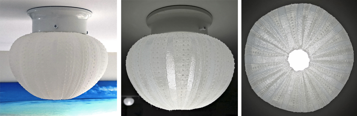
This tutorial will show you how I used completely free software to create a complex object during my time in the MIT course “Additive Manufacturing: From 3D Printing to the Factory Floor” as part of a group project, and is actually very quick once you become familiar with the programs. This particular design combines a hollow object with an internal lattice structure suitable for SLA printing on a printer like the Form 2 from Formlabs, which is what was used for the translucent version in the photo above. The white version in the background is a cross-section view of what is going on within the SLA print.

Step 1: The Overall Form

Clip 01 - 01

There are loads of free programs to use for creating 3D models – Tinkercad, Sketchup, Openscad, Sculptris, Fusion 360 (if you’re linked to an educational institution)… there are many more and you can certainly use your favourite. For this project, I actually used Onshape for the first time, which runs completely in the cloud (so no software downloading or limitations on computer operating systems/specifications). If you are at a school or university, you can get a free license. It works very similar to Solidworks or other high-end CAD packages, so if you are familiar with sketches and features, you will pick it up very quickly.

Basically, whichever CAD software you use, you want to create the overall shape of your object. In this case, I created an organic tear-drop shape using a “loft,” and cut a section out of the back so that it would clip onto a desk and act as a bag hook (part of the MIT design challenge).

Step 2: Make it Hollow

Many CAD programs will allow you to “shell” your design, making it hollow inside. However, if you can’t find the tool, or aren’t getting good results, we can do this in the next piece of software. But first, export your solid file as a STL (and if you managed to shell it in this step, export a STL of the hollow version as well and skip the rest of this step. You will still need a solid version for the lattice process).

Meshmixer Hollow

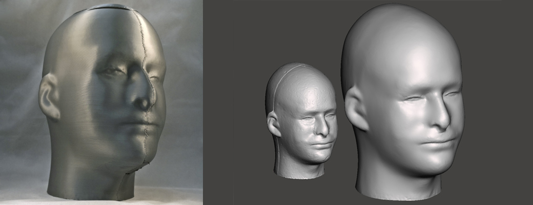
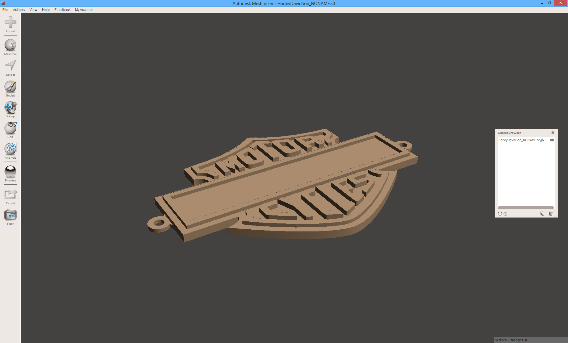
The next free program, which I think is a must for anyone with a 3D printer, is Meshmixer. It allows you to edit the normally un-editable STL file format, and I have previously written tutorials about how to do download files from Thingiverse and combine them in creative ways or add your name to a downloaded part.

If you weren’t able to hollow out your design previously, click on Edit>Hollow and set your wall thickness. Just like that, your solid object is now hollow, and can be exported as a STL.

A note for SLA printing:

Meshmixer Drainage Holes

When using the Form 2 3D printer for the first time, I was surprised to learn that the PreForm software doesn’t allow for the user to specify infill patterns in the same way that is commonly done with FDM printing. That is what created the need for this custom lattice infill, and this tutorial. So, being a liquid resin printer, the final important step is to add drainage holes so that the form doesn’t end up completely full of liquid, and errors don’t occur during printing.

Meshmixer again has this function built in. While in the Hollow tool, you will have the option to “Generate Holes” and manipulate their location. This is really important, as you won’t be able to do it again later once your hollow and lattice are combined (unless you’re familiar with the boolean commands in Meshmixer and manually add a cylinder from the Meshmixer menu to use as a cutting tool).

Step 3: Creating a Lattice

Lattices and 3D printing are best friends. But creating a lattice in many CAD programs is close to impossible, usually requiring advanced skills and a computer that can handle very large patterning features. nTopology Element is a free program that will dramatically simplify the process for you – simply load a STL file, choose a lattice pattern, and boom! your object is now a lattice. But let’s go through it a little more slowly.

1. Import your solid STL file into nTopology Element.

2. On the top menu, click Lattice>Generate

3. In the pop-up, you can play with the lattice patterns (called “Rules”), the size of each lattice volume, and click Generate to get a preview. When you’re happy with the result, click on Apply.

nTopology Lattice Trim

4. You will notice that the result has the lattice coming outside of the original object. This is because only whole lattice volumes are used to fill the object, rather than automatically being trimmed to fit. So we must do this manually. In the top Edit menu, click on the Trim tool. A new pop-up will appear, asking you to select the Lattice geometry and the Trim Volume (original model), which you can select from the drop-down menu on the left. Click apply and the lattice will be trimmed to fit perfectly within your original design.

5. At this point, the lattice is made up of vectors – they have no volume. So the next step is to use the Thicken tool on the top menu to provide a diameter to your lattice.

nTopology Tutorial

6. Lastly, the thickened lattice needs to be turned into a single mesh that can be 3D printed. The Mesh button (where it says Interchange on the top menu) will join everything together and give you a single mesh. In the drop-down menu on the left, you can now right-click on the mesh, and click on export to get your STL file.

Step 4: Bringing it all Together

The free version of nTopology won’t let you stitch multiple files together, however the Pro version will if you ever end up with the need for a full license. So back to Meshmixer to bring it all together ready for 3D printing.

1. Import the hollow STL and lattice STL into Meshmixer (when you click on import for the second file, use the Append option).

2. You will notice that the ends of the lattice stick out from your object. There are 2 ways to correct this: Option 1 is to use the sculpt tool with the “Flatten” brush to go around and push the ends of the lattice inside of the object boundary – it’s just like pushing clay.

Meshmixer Sculpt Lattice

Option 2 is to ever so slightly reduce the scale of your lattice. With the lattice selected in the pop-up Object Browser window (on the right of my window), click on Edit>Transform and you can either manually manipulate the scale, or more accurately type in the reduction in the transform window (with the uniform scaling option ticked). You should only need a small reduction until the lattice fits just inside the outer skin of your object.

3. By turning off the hollow part in the Object Browser, but keeping it selected, you will get an X-Ray view into your object to check if the lattice and hollow part are intersecting. This can help with any final alignment. Remember; you want the lattice touching the solid shell, but not poking through so it’s visible, or loosely floating within the hollow.

Meshmixer Lattice View

4. In the Object Browser, [shift]+click to select both parts at the same time. A new window will appear that will allow you to Boolean Union or Combine both parts together, creating a single object.

5. Export the final STL and you are ready for 3D printing.

SLA Form 2 Print Fresh

Step 5: Getting Creative

Meshmixer Creative Lattice

Once you get a bit of experience with this process and some of the other tools in Meshmixer, your imagination is the limit! You can really begin to play with different combinations of solid and lattice structures depending on the result you want. Have some fun and feel free to share any of your own creations in the comments section.

– Posted by James Novak

Mashup-Yoda – Download For Free

Yoda Header

Recently I wrote a step-by-step tutorial for my friends at Pinshape about how you can use free software (Meshmixer) to combine downloaded STL files into your own unique design – this is called a mashup, or a remix. The tutorial is nice and easy to follow, and was just the start of my plan to create some really interesting designs in a series of mashups. You can find a full video tutorial and links to the written tutorial in my previous post.

Finally I’ve found some time to create mashup number 2, Mashup-Yoda! This design has taken a lot more time to create in Meshmixer, along with learning some of the more advanced tools and plenty of trial-and-error along the way. However it is based on a similar idea as the Mashup-Rex from the tutorial, combining a skeleton element with an external skin to give a cutaway effect to the creature. However, what might Yoda’s skeleton look like?

Yoda's_death

As you (hopefully) know from the film Return of the Jedi, Yoda’s body vanishes as he becomes one with the force in his death, so there is no way to know. But upon finding the Voronoi Yoda model by Dizingof on Thingiverse, it seemed like an interesting concept for this powerful Jedi, perhaps a more organic internal skeleton that was formed by the Midi-chlorians (some real Star Wars nerd talk!) that gave Yoda his power.

Nerd talk aside, as much as anything the Voronoi Yoda just seemed like a cool model that would be fun to combine with a realistic bust of Yoda, also available freely on Thingiverse. The 2 models are a great fit, with the main challenge being the slicing and dicing of the geometry in Meshmixer to create this organic looking, almost cyborg-like Yoda mashup. Mostly this has been achieved using the Sculpt tools and the Select tool to remove sections of the models and re-shape them to look like they were designed this way from the beginning.

20170625_Mashup-Yoda

I’ll admit that I did have some problems combining the 2 models into a single STL file right at the end in Meshmixer, probably due to the weird intersections between the models where I had pushed and pulled surfaces too far into a non-manifold object. I also ended up with a file size of about 87MB, a bit ridiculous for sharing online, and the normal reduction techniques in Meshmixer were just destroying the quality of the surfaces. So I ended up bringing the large STL file into Rhinoceros, reducing the mesh by about 75%, exporting as a STL, importing back into Meshmixer, using the Inspector tool to repair any little remaining errors automatically, and finally exporting a clean, 3D printable STL file. That’s a mouthful!

Now that the hard work’s been done, I’d love you to have this model for free so you can print it out, or even get crazy and try remixing my remix using some of the techniques shown in my Pinshape tutorial! I’ve uploaded it to my favourite 3D file sharing websites Pinshape, Thingiverse, 3D File Market and Cults. Choose your website, 3D print and share some photos 🙂

May the force be with you

– Posted by James Novak

The Meshmixer Mashup: Mashup-Rex!

Tutorial Meshmixer Mashup

The mashup is a favourite technique in the music world that combines two or more songs together into a single song. They might be from completely different eras or genres and when cleverly mashed together, they create a new smash hit. But did you know that creating a 3D printable mashup is just as easy as creating a musical one? Take a bit of File A, mix it with File B, and you now have your own creative design.

Over the last few weeks I’ve been putting together a new tutorial for my friends at Pinshape, which includes my first video tutorial as well as the usual step-by-step process to follow along with. Click here to learn how to mashup STL files in only 10 easy steps using the freely available software Autodesk Meshmixer.

The mashup is often called a Remix in the 3D printing world, and is a great way to build upon other designs and add your own creative touch, or re-purpose a design for a new application. The video tutorial is a real-time look at the process, which with a bit of practice, will have you remixing new designs in a matter of minutes. If you want to follow along, you just need to install Meshmixer on your computer, and download the 2 T-Rex files used in this tutorial which are free on Pinshape:

  1. Low Poly T-Rex by steven_dakh
  2. The T-Rex Skull by harry (we are only using the head piece, not the jaw)

Mashup-Rex

Alongside the tutorial is my latest design, the Mashup-Rex. I have made this available for free on Pinshape, just click here to download the file. Maybe you you will create your own remix of my remix? If you do, or you just 3D print the Mashup-Rex for yourself, please share it on Pinshape to add to the community and see how far the design can go! In the version pictured above I simply used a coffee stain to “age” the skull, similar to my previous print of the Star Wars Deathtrooper. I’m enjoying this simple technique at the moment, although you may like to use a 2-tone print, or go all out with some painted effects.

Happy mixing!

– Posted by James Novak

When Layer Orientation Matters

20160819_Meshmixer Plane Cut

Often when you are 3D printing the main thing you think about is how much support material your print will have, and you orient your print to minimise this – reducing material waste, print time and any manual post-processing to clean up the print. However sometimes the best print orientation for these reasons is not the best for mechanical strength, and I’ve just discovered this with one of the parts for the InMoov robotic arm I’m currently building (see the first collection of 3D prints in my previous post).

The “RobServoBedV6” part is where the 5 servo’s connect that control the individual finger movements, using screws to fix them in place. However some of the stands are splitting as I screw into them as shown in the photo above due to the layer orientation. Yes I could use super glue to fix them, but the split will just happen  somewhere else. So I’m going to completely cut the stands away from the part, and re-print just these stands in a different orientation to improve their strength. This is where the free program Meshmixer comes in very handy, and I’ve previously published a few examples of how to use it for my friends at Pinshape – just click here to find out more.

In the top right image you can see the first step of using Meshmixer to edit the STL file. I have used the Plane Cut tool to slice away the bottom plate, and then repeat the process to remove the other 2 segments which seem to be strong enough for the screws at the moment. This leaves me with the 2 stands that I’m having issues with. These can now be exported as STL’s ready to 3D print (orientation is not important here, this will be set in my 3D print software).

Cura from Meshmixer

I’m printing these parts as we speak on my Cocoon Create 3D printer, and have used Cura to prepare the parts and get the G-code. As you can see to the left, I have oriented the parts so that the layers are perpendicular to the original orientation, meaning that when I screw into them, the force from the screw will not pull the layers apart. Super glue will hold these replacements onto the original part really well as they are printed in ABS.

If you are designing your own parts from scratch in CAD and intend to screw directly into them, keep this issue in mind. However if you’re downloading a STL where modification isn’t as easy, knowing this simple trick in Meshmixer can really help you repair and improve a part rather than trying to re-print it from scratch and potentially use a lot of support material in a different orientation.

– Posted by James Novak

How to Repair STL Files

blog-header-repair-stls

My first blog article for the new year for my friends at Pinshape is now available, and walks step-by-step through a number of common repairs you may need to make to your files prior to 3D printing – just click this link to read all about it and follow along. The main things covered are:

  1. How to repair holes and gaps in surfaces
  2. How to delete or trim unwanted surfaces, particularly useful for 3D scan data
  3. How to add thickness to surface geometry, turning it into a solid
  4. How to reduce file size

All of the tutorials use the freely available software Meshmixer from Autodesk, as it’s by far been the most user friendly tool I’ve found for working with .stl files, however you should have similar success using other free software like MeshLab or netfabb Basic. This tutorial builds upon another similar tutorial I wrote for Pinshape in 2015 called How to Modify an STL File: A Beginner’s Guide which shows you how to take a downloaded .stl (or one of your own) and begin customising it for your own needs, for example adding text onto the design.

I hope it helps improve your designs and your 3D printing success rate 🙂

– Posted by James Novak

1/2/2016 UPDATE: A new version of Meshmixer has just been released – Makezine has just posted a really good summary of some of the exciting new features http://makezine.com/2016/01/30/autodesk-releases-meshmixer-3/

UPDATE 30/03/2016: With the sad news that Pinshape has closed down (read more here), you can now read this article in the PDF below.

Click here to open the PDF