Did you know it’s possible to knit using a desktop 3D printer?
This has been some work I’ve been doing in the background for a little while now and combines all the benefits of digital design with craft-based hand assembly. OK, so you can’t print with soft yarn (yet), but by printing thin geometry you can create some relatively soft and flexible knits that are unlike the typical chainmail assemblies often used in 3D printed fashion/textiles.
The trick to this is to simplify the knit into individual pieces, which can be 3D printed flat on the build plate. This makes printing extremely fast, also known as a 2.5D print which I’ve written about in a previous blog post. While one of the benefits often discussed about 3D printing is the ability to produce complex assemblies as a single part, in the case of a knit, this will result in significant amounts of support material, and the need for quite bulky geometry to ensure the knit geometry is strong enough. However, by printing separate components, these problems are avoided, and you can have some fun manually connecting the loops together while you wait for the next print.
Additionally, the new opportunity of 3D printed knits is to create completely new patterns and geometries in CAD software. This has been the focus of my newly published paper called A Boolean Method to Model Knit Geometries with Conditional Logic for Additive Manufacturing (free to access). In it I detail how to set up an algorithm in Rhino with Grasshopper that will allow customisation of loop and float structures for a knit, the sort shown in the top picture. If you have some experience with the software, you can follow the process outlined in the paper to set up a similar system, and begin modifying parameters and geometry to create completely new knits that would not be possible using traditional knitting techniques.
As shown above, the Grasshopper code gets quite complex so is not for the feint of heart, but if you understand boolean logic, and have used Grasshopper, I’m sure you can build this! And if not, have a go at modelling some knit geometry in your favourite CAD package and print it out – you can keep printing on repeat to extend the size of your “knitted” textile, this is how some of my early tests were done. If you start by modelling some rows of circles, then connect them together, this will get you close to a knit structure.
I’ve been throwing out teasers about this project on social media for over a year, and with my research just published in the Rapid Prototyping Journal, it is very exciting to finally be at the finish line and able to share it – all of it! So what exactly is it?
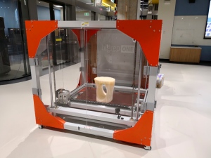
Well, it’s a 3D printed stool. But more than that, it’s the outcome of a design for additive manufacturing case study using the new BigRep ONE 3D printers, housed in the ProtoSpace facility at the University of Technology Sydney. The BigRep ONE is essentially a desktop FDM 3D printer on steroids, with a build volume measuring 1005 x 1005 x 1005mm, that’s over 1 cubic meter of space to 3D print! And much like a desktop FDM printer it uses filaments like PLA, PETG, TPU and realistically just about any other filament material, as well as using a Simplify3D profile for slicing, so designing for the printer and operating it is identical to many common desktop 3D printers.
Given the newness of these machines when they were installed in ProtoSpace in early 2018, my job was to test the capabilities of them whilst developing a showcase product to highlight how they can be used to develop new types of products, and with such a large build volume, furniture was an obvious choice. However, my budget was not unlimited ($1500 AUD) and nor was the time I was allowed to run the printer, which was capped at 5 days so that it was not taken out of commission for other users for more than one working week. Sounds like a generous timeframe unless you’re familiar with just how slow FDM printing is even at the desktop scale, and while this printer is bigger, it is certainly not any faster. And when you are printing for 5 days, this machine will really chew through filament, so that $1500 budget quickly runs out.
In terms of the fingerprint concept, the stool was designed when I was newly engaged and uses a fingerprint from my (now wife’s) ring finger, and my own. Awwwwe… There are few features more unique to each human than a fingerprint, so this concept was also chosen as a truly unique feature that highlights the capacity for 3D printing to be used for one-off personalised products.
The above video helps explain the design and printing process, which essentially involved:
Ink used to take impressions of fingerprints on paper.
Fingerprints digitised using a flatbed scanner.
Fingerprints vectorised in Adobe Illustrator. Exported as DXF files.
DXF files imported into Solidworks CAD software and oriented 420mm apart for the height of the stool.
Manual creation of the 3D geometry.
Export to STL.
Slice in Simplify3D.
3D print on the BigRep ONE [1mm nozzle diameter, 0.5mm layer height, 5% infill, 2 walls, 3000mm/min print speed]
Sounds nice and straight forward. However, I must admit things did not go this smoothly: Firstly, designing to fit a specific budget and print time required several iterations, with an early version of the design twice as large as the design pictured here. This meant initial cost estimates were in the range of $2194-3882 and print times 117.5-216.1hours – talk about variation! All of this variation is due to experimenting with process parameters like layer height and nozzle diameter for the same design, and was an important learning process that could be taken back into later iterations of the design, which ultimately became smaller.
Secondly, another obstacle we struggled with was bed adhesion. This is a common problem with desktop machines, however, not normally when printing with PLA. We quickly found that during the first layers, a slight warp or piece of material sticking up would get knocked by the extruder, causing a knock-on effect as the extruder and any material it had collected quickly cause all of the individual sections of the fingerprint to dislodge. Pictured above on the left is the largest section that printed before some material snapped off and somehow caused the nozzle to become entombed in PLA, pictured above on the right. That was an expensive error, new nozzles for the BigRep ONE do not come cheap!
Given the design was intended to print without any need for support material, we eventually had to concede defeat and add a raft. This had the effect of linking all of the initially individual sections of fingerprint together during the first layers, and provided a strong adhesion to the bed. While we could’ve tried all sorts of glues, tapes and other hacks, we didn’t want to resort to these on such a new machine until we had more time to test settings and work with BigRep on a solution. The good news: the raft worked and after 113 hours, and at a cost of $1634 (only slightly over budget), the Fingerprint Stool was complete. The raft did take 1 hour to remove with a hammer and chisel (with a 1mm nozzle there is so much material it cannot be removed by hand), and the surface finish is quite rough – but in my mind this is the charm of FDM, just like a piece of timber has grain and knots that are simply part of the material.
Overall the BigRep ONE is an exciting technology, you just need to keep in mind that due to the scale, all of the small issues you can experience on a cheap desktop machine are also magnified. However, it is great for producing large-scale functional parts like furniture, or any of the other examples you may have seen from BigRep in 3D printing news over recent months.
This is a brief overview of the project, there is much more technical information and analysis in my paper in the Rapid Prototyping Journal, including metrology data of the final design compared with the 3D file, as well as surface roughness data. I’d love to hear your feedback on the project or your own experiences with the printer if you’ve been lucky enough to use one. And keep an eye out for updates about the stool appearing in an exhibition later in the year 😉
UPDATE: Thank you to BigRep for taking an interest in this project and writing their own story about it here, and to 3D Printing Industry for also sharing this story.
As a university researcher, it often takes a long time until I can actually share my work publicly. As a result this blog often only tells part of the story, for example I recently posted about 3D printing a prosthetic hand by e-NABLE. What I didn’t say is that this was part of research into adapting the design to perform different tasks. Recently undergraduate product design student Cory Dolman worked with me to prototype some new concepts, and his work has been picked up by UTS who created this great video about his process and the ideas we’ve been bringing to life. You can also read all the details on his blog which was maintained during the project with me here.
For anyone who is yet to realise the opportunities of 3D printing technology, hopefully this video goes some way to showing how quickly designers like Cory and myself are able to iterate designs, constantly testing our ideas and expediting the design process. We hope that as we refine these designs, we will be able to share them back into the e-NABLE community, and allow anyone with access to a 3D printer to not only benefit from the prosthetic, but also continue to iterate and improve it collaboratively. This is what excites me about 3D printing – it’s not just about the technology, but what it enables.
If you’ve been paying any attention to 3D printing over recent years, no doubt you’ve seen at least a few 3D printed prosthetics. From the Iron Man prosthetic arm to the prosthetics being 3D printed for our animal friends, 3D printing is ushering in a new generation of low-cost, customisable prosthetics. Perhaps you’ve even seen my build of the fully robotic InMoov hand which has been documented on this blog.
At the extremely affordable end of the spectrum for humans, Enabling the Future (also called e-NABLE) is one of the most well-known names, developing a range of open source prosthetics since 2013, which can be freely downloaded, printed, assembled and sent off to those in need. As part of my research I have wanted to build one of the e-NABLE hands for a while now to understand more about them, particularly in comparison to the more complex InMoov robot arm. As pictured above, I’ve finally got around to printing the Phoenix v2 hand, which is wrist actuated to open/close the fingers.
When you look at all the details, it really is a clever design which is optimised for 3D printing on a desktop FDM machine, with almost no support material or waste, and tolerances that fit really well together. Anyone with a 3D printer could assemble one of these, most of the non-3D printed parts can be sourced at a local hardware store or found in your shed (screws and fishing line). The instructions are very clear, and there are loads of videos to help demonstrate the assembly process and how some of the technical aspects of the hand work. Because I printed in ABS rather than PLA plastic, the only small hurdle I had was in the thermoforming process of the gauntlet (the bent white piece that mounts to the users arm), which required me using a strip heater in the university workshop. If you find yourself in a similar situation, you can check out the details which were posted in one of my previous posts. However, I recommend using PLA if you have the choice to make this part easier, only requiring some boiling water as demonstrated in this video. In itself, this is a really cool technique that I will use in the future to create stronger parts; you can always learn a lot from 3D printing other people’s designs.
Overall the e-NABLE community really has done a great job in refining this design over the years, and I’m already working on some of my own iterations which will hopefully be fed back into the e-NABLE community in the future. If you’re looking for a project to build and learn from, or potentially getting involved in the community and building hands for people in need, Enabling the Future is definitely worth researching.
During November 2017 I was lucky enough to be involved in a 2-day workshop run by Lionel Dean from Future Factories. Lionel has been working with 3D printing for many years, and his work is very inspirational – I’d recommend taking a look at his projects which all use algorithms to generate complex, one-off products often 3D printed in precious metals like gold. The projects really highlight the capabilities of 3D printing and push the boundaries of what is possible.
The workshop focused on using Grasshopper, which runs as a plugin for the 3D modelling software Rhino. If you’ve been following this blog for a while you’ve probably seen a few videos and demonstrations as I’ve been learning the program, including my successful Kickstarter earlier this year. The video above is the final simulation produced by the end of the workshop, which was an exploration of mimicking natural growth processes, similar to a sprouting seed. It’s not perfect, but definitely highlights the opportunities of using algorithms to design, as opposed to manually creating a singular static form. In Lionel’s work, he often uses these forms of growth to allow people to essentially pause the simulation and have the particular “frame” 3D printed as a custom object.
For any fellow Grasshopper geeks, above you can get an idea of the code used to generate these sprouts. There is no starting model in Rhino, it is entirely built from this code. Hopefully this will influence some future projects…
Sorry for the blogging silence, this is the longest break I’ve had since starting a number of years ago. Long story short I’ve made a big move recently for work and am only just starting to get back into printing and making new projects. If you follow my social media, you’ve probably noticed some new things starting!
One of the projects I’ve wanted to play with since previously building the InMoov robot arm is the Enabling the Future prosthetics (aka. e-NABLE). This week I 3D printed and built most of the Phoenix v2 hand, which of course is open source and free to download. A really inspiring company, and a vastly more simple design compared to the electronic InMoov! Some of the pieces, which I printed on an UP Mini 2 in ABS plastic, can be seen above. I’ll post full details once I get it up and running, just waiting on some elastics for the fingers. The gauntlet piece, which attaches to the users forearm, is printed in a flat position and then bent into a C shape afterwards. This is a really clever idea for providing the strongest functional part with optimal layer orientation. But how do you bend a 3D print?
Well the instructions from e-NABLE require dipping the piece in boiling water for a few seconds to make it pliable – if you 3D print in PLA, which has a lower melting temperature than ABS. Check out the video here. However ABS is not really going to be affected by boiling water, and just to make sure I did try this technique with my first print. It did get a bit of a bend, but mostly a snap!
For print #2 I instead found myself a strip heater in the workshop, which is perfect for heating a nice clean line and normally used to bend acrylic sheets. A few seconds on each side of the print and it bent perfectly without de-lamination or splitting, and was easy to re-heat to make small adjustments to fit with the hand print. This is a technique I’d never thought of using, but has really given me a lot of ideas for creating 3D prints which are post-processed like this into a stronger shape than if they were 3D printed in their final more complex form. I think some of the simple enclosures I’ve made in the past could be much stronger if considered more like a sheet-metal part, although then this begs the question why not just laser cut the design? Well in the case of this e-NABLE prosthetic, there are some 3D details for snapping in other pieces, which could not be done using a 2D process like laser cutting. This would be important to consider if using this process with 3D printing, but it’s certainly an interesting technique worth further experimentation.
If you’ve done something like this yourself, or have ideas for thermoforming a 3D print, leave me a comment.
3D printing insects and creatures is nothing new, but maybe the months written on the image above indicates something more is going on with these 3D prints…
The 3D models of the caterpillar and butterfly are in fact generated by monthly step data collected on my old Garmin Vivofit – no design (or designer!) required. This is all an experiment to explore how non-designers may be able to use 3D printers without needing to learn complex CAD software, or sit on websites like Thingiverse and download random things just for the sake of printing. With the proliferation of activity trackers and smart watches gathering this data, perhaps there are creative ways for software to generate rewards from this data, which can be sent to a 3D printer and turned into something tangible?
I won’t go into all the details and theories right now, this work will be presented at the Design 4 Health conference in Melbourne this December. Visitors will even be able to input their own daily, monthly or yearly step goals, along with their actual steps achieved, and generate their own rewards. This is all controlled in Rhino with Grasshopper using some tricky parametric functions to automatically grow a caterpillar into a butterfly; if the steps achieved are below the goal, you will have a caterpillar, with the number of body segments growing depending on the percentage of achievement towards the goal. If the goal has been exceeded, a butterfly will emerge and grow bigger and bigger as the steps achieved continue to increase over the goal. You can see the results for a number of months of my own data tracking in the image above.
The 3D prints are being done in plastic for the exhibition, the examples above done on UP Plus 2‘s, however there’s no reason a future system couldn’t use chocolate or sugar as an edible reward for achieving your goals! I think it will take some interesting applications of 3D printers such as this to ever see a 3D printer in every home as some experts have predicted. But as anyone with a 3D printer knows, it will also take far more reliable, truly plug-n-play printers to reach this level of ubiquity. Time will tell.
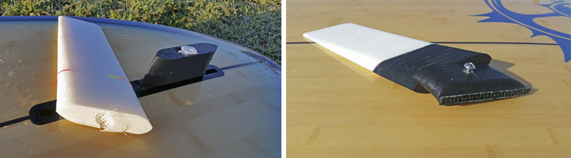
Behind the scenes I’ve been working on a Stand Up Paddle (SUP) fin project for quite a while now, 3D printing many prototypes, and more often than not, failing! There is more to this project than meets the eye, but for now the details are under wraps. However I thought it might be interesting to share some of the 3D prints in case anyone feels inspired to give it a go themselves.
The design pictured above is the first one that worked successfully without breaking or having other technical issues. Printed in 4 pieces on my Cocoon Create due to the size, it required a bit of gluing, and as you can see from the pink highlight, a bit of gap filling with a 3Doodler Pen (if you want to know more about using a 3D printing pen as a gap filler, check out one of my previous posts all about it). As a result the fin is about 400mm long, huge compared to the fin that came with the board (which for any SUP fans out there is a Slingshot G-Whiz 9’4″)
These images show some of the breakages I’ve had due to layer delamination – unfortunately the optimal way to print the 4 pieces in terms of minimising support material and warping is vertical, however the optimal orientation for strength is laying down on the flat sides (similar to the image on the right). A bit of an oversight on my part I’ll admit, however I was genuinely surprised how much force the flat water put on the fin. Another issue may be the minimal infill, which was also beefed up in my later prints to add internal strength. There is always a delicate balance between print orientation, layer strength and infill in 3D printing, to name just a few!
The main thing is that the fin prototype now works, and I may have a more advanced version being printed using Selective Laser Sintering (SLS) as I write this… If you keep an eye on my blog by subscribing below, you may just get to see where this project is going 🙂
Through the month of January Kickstarter are running the Make 100 Challenge, and I was inspired to set something up quickly that would be a bit of fun for both myself and potential backers. The idea of the challenge is to get something off the ground that is limited to 100 editions, so it’s inspiring to see a lot of new projects that might not normally launch on Kickstarter, many of them quite creative and artistic. That’s where I’ve pitched my Kickstarter – something a bit unusual and creative, yet fitting in with my interests of customization, hacking, digital manufacturing, algorithms, coding, parametric design, CAD… All the fun stuff.
On paper the idea is relatively simple – send me a photograph, I use some software to generate a Picasso-like line drawing, and that drawing gets sent to my hacked Solidoodle Press to be drawn on paper. But hopefully the video shows that the process is a little more complex than that, and quite interesting to watch.
I would love you to take a look, share the link, or if you’re really interested help get this project off the ground with funding levels starting at only $8 for the final eBook compilation. Whatever happens it’s been a great experience to put this campaign together.
– Posted by James Novak
22/1/2017 UPDATE: To thank everyone for your support and reaching the 200% funding milestone, here’s a new short video showing what happens when Robot Picasso draws a cliff-top building.
Robot Picasso also has a new Facebook Page you can follow to keep up to date with the latest developments. Let’s keep the momentum of this campaign and try and get 100 unique drawings!
3D printing is awesome for creating so many things – I’ve certainly lost track of how many things I’ve made and shared on this blog! But it’s also fantastic to use alongside traditional manufacturing techniques – moulds for casting, jigs to help in assembly, or in this case, as moulds for vacuum forming. The short video above shows this process being demonstrated to the Intro to 3D Printing class at my university. The faces are 3D printed from 3D scans in ABS plastic, and we are using 1.2mm PETG plastic for the vacuum forms.
The results are really detailed – even the layers from the FDM process have been transferred to the vacuum forms as a texture! After a few of these being created some visible melting of the prints was visible, mostly on the chin and nose where the initial contact with the hot PETG sheet is made – so I’m not sure how long they would last if you were to make 100 of these or more. But a great example of how quickly and easily you can create many copies of a part using the relatively simple method of vacuum forming – you could probably create one of these every 2 minutes, with the plastic only needing 23 seconds to heat before the vacuum process. I know I’ve got some ideas from seeing this.


 Given the newness of these machines when they were installed in ProtoSpace in early 2018, my job was to test the capabilities of them whilst developing a showcase product to highlight how they can be used to develop new types of products, and with such a large build volume, furniture was an obvious choice. However, my budget was not unlimited ($1500 AUD) and nor was the time I was allowed to run the printer, which was capped at 5 days so that it was not taken out of commission for other users for more than one working week. Sounds like a generous timeframe unless you’re familiar with just how slow FDM printing is even at the desktop scale, and while this printer is bigger, it is certainly not any faster. And when you are printing for 5 days, this machine will really chew through filament, so that $1500 budget quickly runs out.